The smallest Pi
Using a 7-segment display with Raspberry Pi Pico
Almost two years passed since the release of the Raspberry Pi Pico. The newer Wi-Fi capable model W has also been released since then. Naturally, I ordered both of them but it took a long time to get to the point to actually use them to do something. But the day finally came.
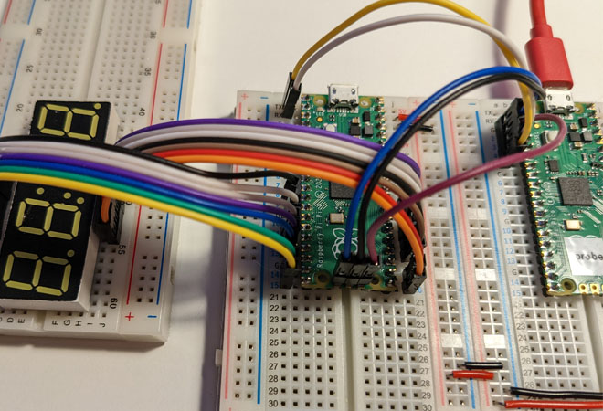
I'll drive a 4 character 7-segment display with it using the Pico's PIO (programmable IO). These things are small state machines inside the Pico and you can run assembly code on them.
Preparations
The official documentation is quite comprehensive about setting up a development environment so I won't go into details here.
The default process is not that developer friendly: you build the program, unplug the USB cable from the Pico, hold down the button on the Pico, plug back the USB cable, drag and drop your U2F file into the storage and we are done. What can I say, it kills the mood a bit. Luckily there are alternative solutions.
In the end I went with the Picoprobe + CLion direction, this way I could debug the new code on the Pico with a press of a button in the IDE. First I started to set this up on Windows, but I gave up on the "build OpenOCD with MSYS2" part and switched to Linux. Maybe I'll give it another try with WSL2 if I need some challenge. Beside the official documentation this tweet helped a lot setting up everything.
The display
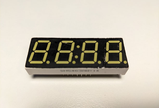
The SH5463AW-14
We need to turn on and off 33 segments (the central : counts as a single segment) that make up the characters and the extra dots. And we only have 14 pins to do this. Something strange is going on here. The trick is that we can only turn on one character at a time. Good news is that if we switch between characters really quick the lame human eyes will think that all four are lit.
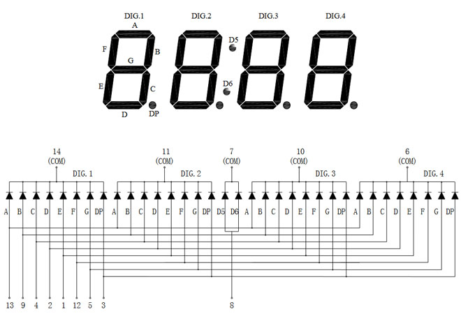
To turn on a specific segment we have to set the pin in the bottom row to 1 and the COM pin in the top row to 0. If we want to display the same character in multiple places we can set multiple COM pins to 0, but in reality it might not worth the hassle.
Let's look at a - not so - short example. Let's say we want to display 12:34:
- set pin
9and4to 1 and pin14to 0 - wait a bit
- set pin
13,9,2,1,5to 1 and pin11to 0 - wait a bit
- set pin
8to 1 and pin7to 0 - wait a bit
- set pin
13,9,4,2,5to 1 and pin10to 0 - wait a bit
- set pin
9,4,12,5to 1 and pin6to 0 - wait a bit
- jump back to step one
If we won't jump back to the beginning and do this till the end of time then we would see the numbers lit up on the display only for a brief moment.
First try
First I wanted to transform the process above into C code. With that I can test that I properly understanded the display datasheet, the Pico SDK documentation and I wired it properly. At this stage using PIO would be an unnecessary complication. The whole code is on Github.
Let's start with some configuration:
c_only.c
const uint pin_map_display_to_pico[] = {
  0,
  16, 17, 18, 19, 20, 21, 22,
  9, 10, 11, 12, 13, 14, 15,
};

const uint A  = pin_map_display_to_pico[13];
const uint B  = pin_map_display_to_pico[9];
const uint C  = pin_map_display_to_pico[4];
const uint D  = pin_map_display_to_pico[2];
const uint E  = pin_map_display_to_pico[1];
const uint F  = pin_map_display_to_pico[12];
const uint G  = pin_map_display_to_pico[5];
const uint DP = pin_map_display_to_pico[3];
const uint D5 = pin_map_display_to_pico[8];

const uint COM_1    = pin_map_display_to_pico[14];
const uint COM_2    = pin_map_display_to_pico[11];
const uint COM_3    = pin_map_display_to_pico[10];
const uint COM_4    = pin_map_display_to_pico[6];
const uint COM_DOTS = pin_map_display_to_pico[7];
I skipped the D6, it's the same as the D5. The pin_map_display_to_pico array contains which display pin corresponds to which Pico pin (zero is not valid). On the Pico I used pins 9 to 22.
c_only.c
stdio_init_all();
for (int i = 1; i < sizeof(pin_map) / sizeof(pin_map[0]); ++i) {
    gpio_init(pin_map[i]);
    gpio_set_dir(pin_map[i], GPIO_OUT);
}
Some more initialization before getting to the point. We have to set all the pins to output mode. Then we can write a long infinite loop that does almost the same thing that we discussed before.
c_only.c
// select and display the colon
gpio_put(COM_DOTS, 0);
gpio_put(D5, 1);

while (true) {
  // select the first character place
  gpio_put(COM_1, 0);
  gpio_put(COM_2, 1);
  gpio_put(COM_3, 1);
  gpio_put(COM_4, 1);

  // display a one
  gpio_put(A, 0);
  gpio_put(B, 1);
  gpio_put(C, 1);
  gpio_put(D, 0);
  gpio_put(E, 0);
  gpio_put(F, 0);
  gpio_put(G, 0);
  gpio_put(DP, 0);

  // wait a bit
  sleep_ms(2);

  // select the second character place
  gpio_put(COM_1, 1);
  gpio_put(COM_2, 0);
  gpio_put(COM_3, 1);
  gpio_put(COM_4, 1);

  // display a two
  gpio_put(A, 1);
  gpio_put(B, 1);
  gpio_put(C, 0);
  gpio_put(D, 1);
  gpio_put(E, 1);
  gpio_put(F, 0);
  gpio_put(G, 1);
  gpio_put(DP, 0);

  // wait a bit
  sleep_ms(2);

  // select the third character place
  gpio_put(COM_1, 1);
  gpio_put(COM_2, 1);
  gpio_put(COM_3, 0);
  gpio_put(COM_4, 1);

  // display a three
  gpio_put(A, 1);
  gpio_put(B, 1);
  gpio_put(C, 1);
  gpio_put(D, 1);
  gpio_put(E, 0);
  gpio_put(F, 0);
  gpio_put(G, 1);
  gpio_put(DP, 0);

  // wait a bit
  sleep_ms(2);

  // select the fourth character place
  gpio_put(COM_1, 1);
  gpio_put(COM_2, 1);
  gpio_put(COM_3, 1);
  gpio_put(COM_4, 0);

  // display a four
  gpio_put(A, 0);
  gpio_put(B, 1);
  gpio_put(C, 1);
  gpio_put(D, 0);
  gpio_put(E, 0);
  gpio_put(F, 1);
  gpio_put(G, 1);
  gpio_put(DP, 0);

  // wait a bit
  sleep_ms(2);
}
The only difference is that the colon does not depend on any other characters (they do not share pins) so we can turn it on at the very beginning and forget about it. It's worth checking it out that this way the : lights up more than the rest of the characters.
A little bit of PIO
I wanted to start with something simple here also just to see that everything is working properly. And the code for this is on Github as well.
basic_pio.pio
.program basic_pio

.define PUBLIC pin_count 14

loop:
  pull
  out pins, pin_count
  jmp loop
The pull gets the 32 bit of data sent by the C code (and blocks the execution until the data arrives) and the out will write out 14 bits to the pins we specified earlier (the rest of the data will be overwritten by the next pull) and we start the whole thing all over. The publicly defined pin_count will be accessible by the C code as basic_pio_pin_count.
Where did we specify the pins in use? The PIO file has a little bit of C code that sets up the whole program (I wouldn't say that I like mixing up languages in a single file and the CLion didn't like it either, but that's the way it is):
basic_pio.pio
% c-sdk {
static inline void basic_pio_program_init(PIO pio, uint sm, uint offset, uint pin) {
  pio_sm_config config = basic_pio_program_get_default_config(offset);

  sm_config_set_out_pins(&config, pin, basic_pio_pin_count);

  for (uint i = 0; i < basic_pio_pin_count; ++i) {
    pio_gpio_init(pio, pin + i);
  }
  pio_sm_set_consecutive_pindirs(pio, sm, pin, basic_pio_pin_count, true);

  pio_sm_init(pio, sm, offset, &config);
  pio_sm_set_enabled(pio, sm, true);
}
%}
Next is the C code that uses this PIO program. We send 32 bits of data to the program but only 14 bits will be really useful. These 14 bits will define the state of the 14 pins. The first bit from the right is the value of pin 9 and the last bit is the value of pin 22.
//                             pin 9
//                                 v
uint example_data = 0b00010000000010;
//                    ^
//                    pin 22
We can define some helper constants so we can construct the numbers more easily. Defining the COMs is a bit strange because we have to set every other COM to one, not the one we want to use.
basic_pio.c
#define START_PIN 9

#define A  1 << (14 - START_PIN)
#define B  1 << (10 - START_PIN)
#define C  1 << (19 - START_PIN)
#define D  1 << (17 - START_PIN)
#define E  1 << (16 - START_PIN)
#define F  1 << (13 - START_PIN)
#define G  1 << (20 - START_PIN)
#define DP 1 << (18 - START_PIN)
#define D5 1 << (9 - START_PIN)

#define COM_1    1 << (15 - START_PIN)
#define COM_2    1 << (12 - START_PIN)
#define COM_3    1 << (11 - START_PIN)
#define COM_4    1 << (21 - START_PIN)
#define COM_DOTS 1 << (22 - START_PIN)

const uint one   = B|C|D5;
const uint two   = A|B|D|E|G;
const uint three = A|B|C|D|G;
const uint four  = B|C|F|G|DP;

const uint com_1 = COM_2|COM_3|COM_4;
const uint com_2 = COM_1|COM_3|COM_4|COM_DOTS;
const uint com_3 = COM_1|COM_2|COM_4|COM_DOTS;
const uint com_4 = COM_1|COM_2|COM_3|COM_DOTS;
A little bit of a trick here is that we hid the display of the : into the one variable. This way we get rid of the more shiny : problem as well.
To use the PIO program we have to include the header file generated by CMake. For me this was a #include "basic_pio.pio.h" line at the top of the C file. And we can continue with setting up the program.
basic_pio.c
const PIO pio = pio0;

const uint offset = pio_add_program(pio, &basic_pio_program);
const uint sm = pio_claim_unused_sm(pio, true);

basic_pio_program_init(pio, sm, offset, START_PIN);
We add the program, get a state machine of our own and initialize it.
Only the display logic is left for us to do now. It's a bit shorter than the C-only solution but it basically does the same thing.
basic_pio.c
while (true) {
  pio_sm_put(pio, sm, com_1|one);
  sleep_ms(2);
  pio_sm_put(pio, sm, com_2|two);
  sleep_ms(2);
  pio_sm_put(pio, sm, com_3|three);
  sleep_ms(2);
  pio_sm_put(pio, sm, com_4|four);
  sleep_ms(2);
}
The final result
In the last example the timing of the display was still handled by the C code which is not an ideal situation if you also want to do something else in the code beside driving the display. It would be nice if we could just pass the PIO all the data and it would just take care of all the things display related.
To display all four characters we need four times 14 bits of data, so a 32 bit variable won't be enough. Lucky for us that the state machine has two registers we could use (x and y), so we could send the content of the display as two 28 bit data. The PIO program would store those data into the two registers and send it out to the GPIO in 14 bit chunks with the right timing.
advanced_pio.pio
.program advanced_pio

.define PUBLIC pin_count 14

.wrap_target
  mov isr, x
  mov x, y
  mov y, isr

  pull noblock
  mov x, osr

  out pins, pin_count [5]
  out pins, pin_count
.wrap
The .wrap_target/.wrap part is just like a loop:/jmp loop around the whole thing but it does not cost an extra instruction.
In the first block we switch the contents of the x and y registers. We use the isr (Input Shift Register) as a temporary storage for this. It's not a problem because it isn't in use in our case (it would hold the data coming from the GPIO if the pins would be in input mode).
Next thing is a non-blocking pull instruction. It would put the data coming from the C code into the osr (Output Shift Register, data going to the GPIO pins). A nice property of a non-blocking pull is that if we don't have data then it will use the data from the x register. This way we already solved that if we don't have new data we will display the old data.
Next we will send out 14 bits of data to the pins two times. The [5] at the end of the first out is a five instruction long delay so from the point of the display there will be the same amount of delay after each out call.
The end result will be that we get the data from x and y in turns and we update the data in the registers in turns as well.
And of course we have a similar initialization function for this PIO program as well.
advanced_pio.pio
% c-sdk {
#include "hardware/clocks.h"

static inline void advanced_pio_program_init(PIO pio, uint sm, uint offset, uint pin) {
  pio_sm_config config = advanced_pio_program_get_default_config(offset);

  sm_config_set_out_pins(&config, pin, advanced_pio_pin_count);

  float clock_divider = (float) clock_get_hz(clk_sys) / 2000000;
  sm_config_set_clkdiv(&config, clock_divider);

  for (uint i = 0; i < advanced_pio_pin_count; ++i) {
    pio_gpio_init(pio, pin + i);
  }
  pio_sm_set_consecutive_pindirs(pio, sm, pin, advanced_pio_pin_count, true);

  pio_sm_init(pio, sm, offset, &config);
  pio_sm_set_enabled(pio, sm, true);
}
%}
The only difference is that we call sm_config_set_clkdiv function to slow down the state machine so we alternate the numbers on the display at the right pace.
advanced_pio.c
pio_sm_put(pio, sm, ((com_1|one) << advanced_pio_pin_count) | com_2|two);
pio_sm_put(pio, sm, ((com_3|three) << advanced_pio_pin_count) | com_4|four);

while (true) {
  sleep_ms(1000);
}
Most of the C code is the same as the last example as well. We only changed the parts around the infinite loop a bit. We only send the data to the PIO program one time and after that we can do anything in the C code, the display will be updated regardless. And the code for this example is also on Github.