The great count-up
There are numerous ways to build a digital counter
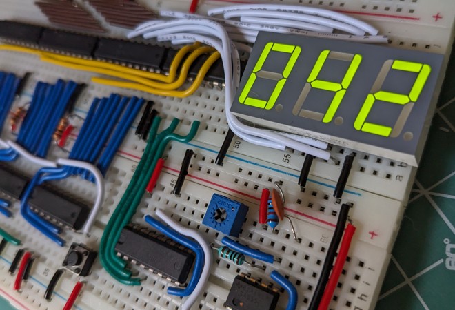
I have had a hardware project in the making for a while now. It's been moving along slowly; I only need to finish the programming part, but I rarely feel like doing it. Because of that, I'm extremely susceptible to distractions.
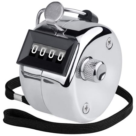
So I saw a mechanical counter in a video. It's not much more than four digits and a button you can use to increment the number. And a knob to zero the whole thing out.
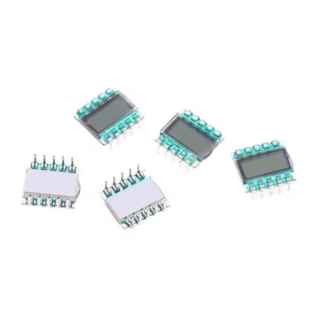
A bit later, I ran into a cute little LCD panel. It can show three digits and, given its dimensions, it looks very breadboard-compatible.
Maybe you can already feel where all this is going. We should build a digital counter. Surely it can't be too complicated. Just a microcontroller, a button or two, a 7-segment display, and a few lines of code. Or is it?
The target hardware
As usual, I didn't go down the easy path. As so many times before, the goal here wasn't actually to make a digital counter. It was just an excuse so I didn't have to work on the other project.
But I didn't want to make my life too hard either, so we won't be making a counter out of just NAND gates. There are specific components out there that can solve parts of our problem. For example, ICs that can count, or ones that understand the segment format of 7-segment displays.
After a bit of searching, I found a chip called the CD4026B, which can count from 0 to 9 and whose output corresponds to the segments of a 7-segment display, from a to g.
                   ┌───┬──┬───┐
             CLOCK ┤ • └──┘   ├ VDD
     CLOCK INHIBIT ┤          ├ RESET
 DISPLAY ENABLE IN ┤          ├ UNGATED "C" SEGMENT OUT
DISPLAY ENABLE OUT ┤          ├ c
         CARRY OUT ┤ CD4026B  ├ b
                 f ┤          ├ e
                 g ┤          ├ a
               VSS ┤          ├ d
                   └──────────┘
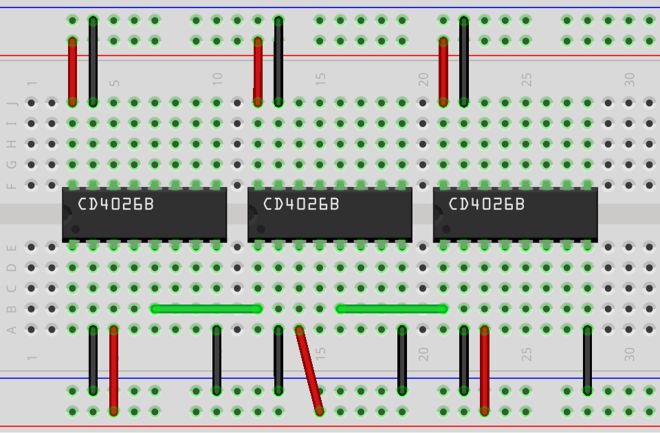
Because of the display, I'm aiming for three digits. The chip's CARRY OUT output becomes 1 when the counter rolls over from 9 to 0, so several CD4026Bs can be chained together to get multiple digits. The CARRY OUT of the lower place value chip has to be connected to the CLOCK of the next higher place value chip.
We could connect the button to the CLOCK input of the lowest place value chip, but buttons have that bad habit called bounce. During a button press, the contacts often touch each other several times, so instead of the expected single increment, our number will increase by some random amount. Not exactly ideal behavior for a counter.
According to the Internet, there are lots of ways to fix this. I recalled a Ben Eater video from the 8-bit computer building series, where this was solved with a monostable 555 timer.
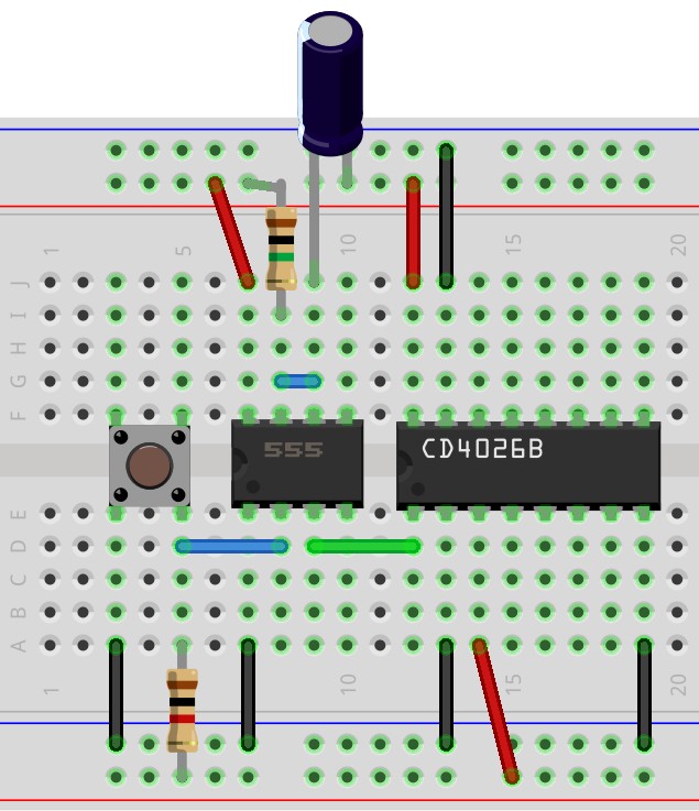
At this point, we have a well-behaved button and three chained ICs, which together can count from 0 to 999. But we can't see their current value.
It turned out that the LCD panel mentioned above is unfortunately not as simple to drive as, say, a 7-segment LED display. Also, it didn't arrive in time, so I used a BC56-12 model instead.
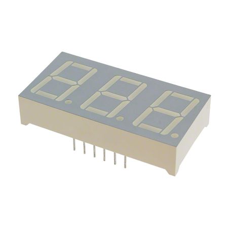
It's worth knowing that all three digits use the same input pins for segments. In addition to those, there are three other inputs that select the currently active digit. So if we want to display three different digits at once, we have to switch between the three inputs very quickly, so that to our eyes it looks as if all three digits are lit at the same time.
There are two versions of this display: common anode and common cathode, depending on whether the anode or cathode ends of the segment LEDs are connected together. Our version is a common cathode.
For the fast switching between the numbers, we'll need a clock signal. Luckily, there's another Ben Eater video from which we can learn to generate a clock signal with the help of an astable 555 timer. We still have to divide this one clock signal into three somehow, so we can use it to select the active digit. I used another counter, the CD4017B, for this.
    ┌───┬──┬───┐
  5 ┤ • └──┘   ├ VDD
  1 ┤          ├ RESET
  0 ┤          ├ CLOCK
  2 ┤          ├ CLOCK INHIBIT
  6 ┤ CD4017B  ├ CARRY OUT
  7 ┤          ├ 9
  3 ┤          ├ 4
VSS ┤          ├ 8
    └──────────┘
Instead of actual segments, this counter indicates its current value on 10 different outputs. We will use the first three numbers to get three mutually exclusive signals, and hook up the fourth number to RESET so it resets itself to zero.

So on one side we have our chained counters with the button, on the other side we have a clock signal split into three, with which we can select the active digit.
There's a promisingly-named DISPLAY ENABLE IN input on our counters. We might think that it could be useful for our situation. But it isn't.
When DISPLAY ENABLE IN is low, all the outputs go low. If they are connected to other outputs that are high (because a segment is turned on in another digit), that creates a short circuit. So it's better not to connect the outputs of our counters together.
Maybe a few (21) diodes could have solved the issue, but I chose the 74HC541 chip invented for this purpose:
     ┌───┬──┬───┐
OE1' ┤ • └──┘   ├ VDD
  A0 ┤          ├ OE2'
  A1 ┤          ├ Y0
  A2 ┤          ├ Y1
  A3 ┤          ├ Y2
  A4 ┤ 74HC541  ├ Y3
  A5 ┤          ├ Y4
  A6 ┤          ├ Y5
  A7 ┤          ├ Y6
 VSS ┤          ├ Y7
     └──────────┘
The input comes in on the A0-7 pins and is output on the Y0-7 pins, if the outputs are enabled (OE1' and OE2'). If the output isn't enabled, then the Y0-7 outputs go into a high-impedance mode and don't interfere with outputs from other ICs.
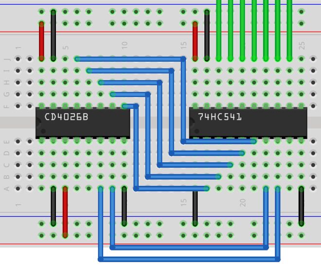
So we connect the a-g outputs of our three CD4026B counters to the inputs of one 74HC541 chip each (the blue wires in the picture), then connect the outputs of the three 74HC541s together (the green wires in the picture) and connect them to the display.
We want to use the signals coming from the CD4017B, which divides the clock signal into three, so that only the appropriate 74HC541 and LED digit are active. But in both places, we need a low signal, while the CD4017B outputs a high signal for the active digit. Fortunately, integrated circuits exist for this too, such as the 74HC240, which inverts the input signal.
     ┌───┬──┬───┐
1OE' ┤ • └──┘   ├ VDD
 1A1 ┤          ├ 2OE'
 2Y4 ┤          ├ 1Y1
 1A2 ┤          ├ 2A4
 2Y3 ┤          ├ 1Y2
 1A3 ┤ 74HC240  ├ 2A3
 2Y2 ┤          ├ 1Y3
 1A4 ┤          ├ 2A2
 2Y1 ┤          ├ 1Y4
 VSS ┤          ├ 2A1
     └──────────┘
We connect our three outputs coming from the CD4017B to the 1A1, 1A2, and 1A3 inputs, and get their opposite values on the 1Y1, 1Y2, and 1Y3 outputs.
With that, we have all the components we need for a working counter. Now we only have to wire everything together, and we're done.
                                                               ╔═════════╗
                        ┌───────────┬───────────┬───────────┬──╢ BC56-12 ║
                        │           │           │           │  ╚═════════╝
                        │           │           │           │
                   ╔════╧════╗ ╔════╧════╗ ╔════╧════╗ ╔════╧════╗
                   ║ 74HC541 ║ ║ 74HC541 ║ ║ 74HC541 ║ ║ 74HC240 ║
                   ╚════╤══╤═╝ ╚════╤══╤═╝ ╚════╤══╤═╝ ╚═╤══╤════╝
                        ┃  └────────╂──┴────────╂──┴─────┘  │
                        ┃           ┃           ┃      ╔════╧════╗
                        ┃           ┃           ┃      ║ CD4017B ║
                        ┃           ┃           ┃      ╚════╤════╝
                        ┃           ┃           ┃           │
╔════════╗ ╔═════╗ ╔════╧════╗ ╔════╧════╗ ╔════╧════╗   ╔══╧══╗
║ Button ╟─╢ 555 ╟─╢ CD4026B ╟─╢ CD4026B ╟─╢ CD4026B ║   ║ 555 ║
╚════════╝ ╚═════╝ ╚═════════╝ ╚═════════╝ ╚═════════╝   ╚═════╝
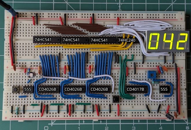
In the picture, you can also see that an extra button is connected to the RESET pins of the three CD4026Bs. It can happen that we start with a random value when the counter is turned on, so it's good to have a reset-to-zero button on hand.
Although the end result looks great, it would be quite uncomfortable to use it as a handheld counter, so I kept looking around for alternative solutions.
Memory helps
At this point, the YouTube Algorithm was probably perfectly aware of what I was up to. It was kind enough to offer me yet another Ben Eater video to watch, this one about driving a 7-segment LED display with an EEPROM.
The components used there are not completely suitable for our purposes, but we can use the basic idea: in the EEPROM, we store in advance which of the 7 segments need to be turned on for a given digit of a given number.
So the input of the EEPROM will be which digit we're currently displaying (3 pins) and which number we're currently at (10 pins, 10 bits, numbers between 0 and 1023). The output will be the state of the seven segments (7 pins). The AT28C64B fits these conditions perfectly: it has 13 inputs and 8 outputs.
     ┌───┬──┬───┐
     ┤ • └──┘   ├ VDD
 A12 ┤          ├ WE'
  A7 ┤          ├
  A6 ┤          ├ A8
  A5 ┤          ├ A9
  A4 ┤          ├ A11
  A3 ┤          ├ OE'
  A2 ┤ AT28C64B ├ A10
  A1 ┤          ├ CE'
  A0 ┤          ├ I/O7
I/O0 ┤          ├ I/O6
I/O1 ┤          ├ I/O5
I/O2 ┤          ├ I/O4
 VSS ┤          ├ I/O3
     └──────────┘
The beginning of the circuit will be very familiar: first, a monostable 555 timer for debouncing the button press, an astable 555 timer for the clock signal, and a CD4017B IC, which splits the clock into three to select the digits. For the counter, we will use the CD4040B, which produces a 12-bit binary output (it can count from 0 to 4095).
    ┌───┬──┬───┐
Q12 ┤ • └──┘   ├ VDD
 Q6 ┤          ├ Q11
 Q5 ┤          ├ Q10
 Q7 ┤          ├ Q8
 Q4 ┤ CD4040B  ├ Q9
 Q3 ┤          ├ RESET
 Q2 ┤          ├ CLOCK
VSS ┤          ├ Q1
    └──────────┘
The data loaded into the AT28C64B performs the conversion between the binary counter and the LED display. The LED display will now be a BA56-12, so we don't have to invert the clock signal (because of the common anode, the selected digit has to be high, while the segment selected to light up has to be low).
First of all, we have to fill the EEPROM with data. I used a Raspberry Pi Pico for this. Fortunately, it has just enough GPIO pins.
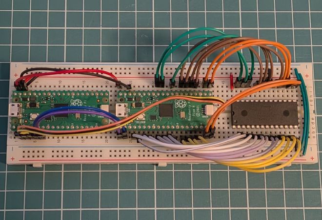
I wrote a little program for it, but I was too lazy to interpret the timing diagrams of the AT28C64B. Instead, I worked with rather large safety margins as far as the sleeps are concerned. This made it fairly slow, but in exchange, it wasn't all that reliable either. I needed to run it multiple times to get the right values in.
#define A0 10
// ...
#define A12 2
#define IO0 11
// ...
#define IO7 18
#define WE 27
#define OE 20

const uint8_t address[13] = { A0, A1, A2, A3, A4, A5, A6, A7, A8, A9, A10, A11, A12 };
const uint8_t io[8] = { IO5, IO7, IO1, IO4, IO3, IO6, IO2, IO0 };

const uint8_t numbers[10][8] = {
    {0, 0, 0, 0, 0, 0, 1, 1},
    {1, 0, 0, 1, 1, 1, 1, 1},
    {0, 0, 1, 0, 0, 1, 0, 1},
    {0, 0, 0, 0, 1, 1, 0, 1},
    {1, 0, 0, 1, 1, 0, 0, 1},
    {0, 1, 0, 0, 1, 0, 0, 1},
    {0, 1, 0, 0, 0, 0, 0, 1},
    {0, 0, 0, 1, 1, 1, 1, 1},
    {0, 0, 0, 0, 0, 0, 0, 1},
    {0, 0, 0, 0, 1, 0, 0, 1},
};
We start with a bit of configuration. We need to map the Pico's pins to the AT28C64B pins. Then we define the order of the address and I/O pins. Finally, we need a mapping of numbers to segment states (on or off).
The order of the address and I/O pins here depends on how we are going to wire the AT28C64B to its inputs and outputs in its final location. In the case of the address, the counter's value will arrive on pins A0-A9. Pins A10-A12 will be used for digit selection. The I/O pins are all over the place just to make the wiring easier between the EEPROM and the display.
int main()
{
    stdio_init_all();

    gpio_init(WE);
    gpio_set_dir(WE, GPIO_OUT);
    gpio_put(WE, true);

    gpio_init(OE);
    gpio_set_dir(OE, GPIO_OUT);
    gpio_put(OE, true);

    for (const uint8_t pin : address)
    {
        gpio_init(pin);
        gpio_set_dir(pin, GPIO_OUT);
        gpio_put(pin, false);
    }
    for (const uint8_t pin : io)
    {
        gpio_init(pin);
        gpio_set_dir(pin, GPIO_OUT);
        gpio_put(pin, false);
    }

    // ...
}
During initialization, we set everything to output and turn everything off. In the case of the WRITE ENABLE and OUTPUT ENABLE pins, this means a high state. After this, we can continue the main function by writing the data.
printf("write\n");
for (int i = 0; i < 1000; ++i)
{
    for (int j = 0; j < 10; ++j)
    {
        gpio_put(address[j], (i & static_cast<int>(pow(2, j))) > 0);
    }

    for (int j = 0; j < 3; ++j)
    {
        gpio_put(address[10], false);
        gpio_put(address[11], false);
        gpio_put(address[12], false);
        gpio_put(address[10 + j], true);

        const int digit = i / static_cast<int>(pow(10, j)) % 10;

        for (int k = 0; k < 8; ++k)
        {
            gpio_put(io[k], numbers[digit][k]);
        }

        sleep_ms(5);
        gpio_put(WE, false);
        sleep_ms(5);
        gpio_put(WE, true);
        sleep_ms(5);
    }
    if (i % 10 == 0)
    {
        printf(".");
    }
}
printf("\ndone.\n");
The first 10 bits of the address are the number we want to display. The last 3 bits indicate the currently active digit. The stored value will be the 7-segment representation of the digit at that place value. For this, we divide the original number by one/ten/one hundred and look at the remainder produced by division by ten.
After setting the values of the address and I/O pins, we turn the WRITE ENABLE pin on and then off again, then move on to the next digit and then the next number.
After programming the EEPROM, all that remains is to connect everything together.
           ╔═════╗ ╔═════════╗
           ║ 555 ╟─╢ CD4017B ╟─┐
           ╚═════╝ ╚═════════╝ │ ╔══════════╗ ╔═════════╗
                               ├─╢ AT28C64B ╟─╢ BA56-12 ║
╔════════╗ ╔═════╗ ╔═════════╗ │ ╚══════════╝ ╚═════════╝
║ Button ╟─╢ 555 ╟─╢ CD4040B ╟─┘
╚════════╝ ╚═════╝ ╚═════════╝
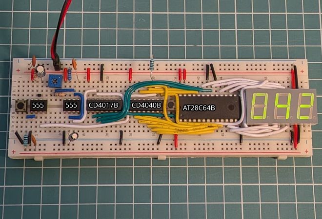
This version did end up half the size of the previous one, but it has its flaws. The counter chip has a 12-bit output, of which we only use 10 bits. With 10 bits, we can count from 0 to 1023, but only three digits are visible on the display. So the dear user will experience that after 999 it counts up to 23, then back up to 999, then up to 23 again, and so on.
In addition, the CD4017B probably cannot supply enough current to properly drive the LEDs, which is why the display is so dim.
Probably neither problem is unsolvable, but they mean extra components, which further increase the size. But what if we want something smaller?
Software solutions
My last idea was the one I had rejected first: a microcontroller. Although a Raspberry Pi Pico would be overkill for such a small task, we can look for something that fits better.
What we need: 7 outputs for the segments, 3 outputs for digit selection, and two inputs for the buttons. The ATtiny24A seems just right. Out of 12 pins, we can use 11 for our own purposes, and the last pin is fixed as RESET, which is just fine, because that's exactly what we need.
       ┌───┬──┬───┐
   VDD ┤ • └──┘   ├ VSS
   PB0 ┤          ├ PA0
   PB1 ┤          ├ PA1
RESET' ┤ ATtiny24 ├ PA2
   PB2 ┤          ├ PA3
   PA7 ┤          ├ PA4
   PA6 ┤          ├ PA5
       └──────────┘
The circuit could hardly be any simpler than this: just the ATtiny24A, two buttons, and the LED display (again, a common anode BA56-12, though in this case we could have used either version; only the segment values would change in the code).
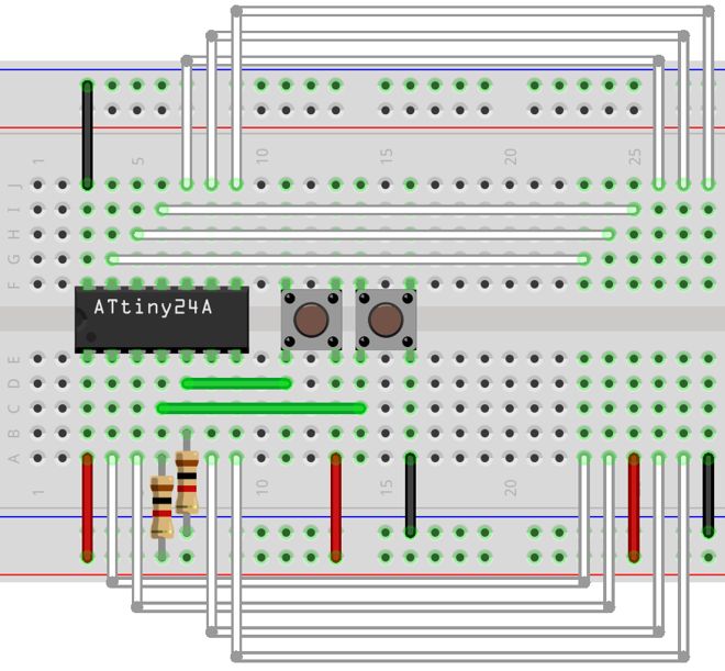
Unfortunately, there wasn't a suitable component for the display, so there's just an empty space where it should be
The reason for the simplicity is that we have to solve everything with software. For this, we have to program the ATtiny. I tried to use a Raspberry Pi for this, but it didn't work for some reason, so in the end I went with an Arduino UNO.
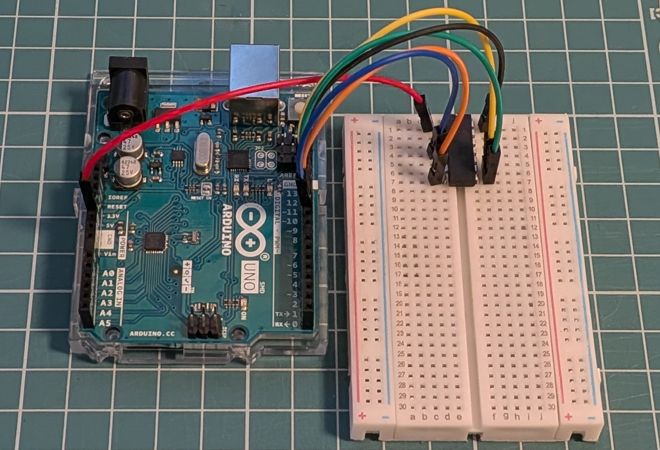
Getting a program onto the ATtiny is not the simplest thing. I won't go into the details, but here is a write-up for it. Let's jump to the programming instead.
const byte digits[3] PROGMEM = {0, 3, 4};
const byte segments[7] PROGMEM = {1, 5, 7, 9, 10, 2, 6};

const byte numbers[10][7] PROGMEM = {
  {0, 0, 0, 0, 0, 0, 1},
  {1, 0, 0, 1, 1, 1, 1},
  {0, 0, 1, 0, 0, 1, 0},
  {0, 0, 0, 0, 1, 1, 0},
  {1, 0, 0, 1, 1, 0, 0},
  {0, 1, 0, 0, 1, 0, 0},
  {0, 1, 0, 0, 0, 0, 0},
  {0, 0, 0, 1, 1, 1, 1},
  {0, 0, 0, 0, 0, 0, 0},
  {0, 0, 0, 0, 1, 0, 0},
};

const byte buttonPin = 8;
The program itself once again begins with a little initialization. We specify the digit and segment pins, as well as the previously used mapping between digits and segments. We store larger variables in program memory (PROGMEM) so that it doesn't take up space in runtime memory. In exchange, it will be a little harder to access them.
void setup() {
  for (byte i = 0; i < 3; ++i) {
    pinMode(pgm_read_byte(&digits[i]), OUTPUT);
    digitalWrite(pgm_read_byte(&digits[i]), LOW);
  }
  for (byte i = 0; i < 7; ++i) {
    pinMode(pgm_read_byte(&segments[i]), OUTPUT);
    digitalWrite(pgm_read_byte(&segments[i]), HIGH);
  }

  pinMode(buttonPin, INPUT);
  attachInterrupt(digitalPinToInterrupt(buttonPin), increment, RISING);
}
We turn off the digit selectors and the segments, and put an interrupt on the button pin. pgm_read_byte is the previously mentioned, more difficult way of accessing data stored in program memory.
volatile byte d0 = 0;
volatile byte d1 = 0;
volatile byte d2 = 0;

volatile bool pressed = false;
volatile unsigned long pressTime;

void increment() {
  if (!pressed) {
    pressed = true;
    pressTime = millis();

    d2 += 1;
    if (d2 > 9) {
      d2 = 0;
      d1 += 1;
      if (d1 > 9) {
        d1 = 0;
        d0 += 1;
        if (d0 > 9) {
          d0 = 0;
        }
      }
    }
  }
}
The interrupt stores the time of the press and increments the digits if the button was not already pressed. This will be the basis of our simple bounce protection.
Storing the digits separately and incrementing them one by one can hardly be called elegant, but we can save a few divisions and remainder calculations in the main loop this way.
void loop() {
  if (pressed) {
    noInterrupts();
    unsigned long t = pressTime;
    interrupts();
    if (millis() - t > 150) {
      pressed = false;
    }
  }

  for (byte i = 0; i < 7; ++i) {
    digitalWrite(pgm_read_byte(&segments[i]), pgm_read_byte(&numbers[d0][i]));
  }
  digitalWrite(pgm_read_byte(&digits[0]), HIGH);
  delay(5);
  digitalWrite(pgm_read_byte(&digits[0]), LOW);

  for (byte i = 0; i < 7; ++i) {
    digitalWrite(pgm_read_byte(&segments[i]), pgm_read_byte(&numbers[d1][i]));
  }
  digitalWrite(pgm_read_byte(&digits[1]), HIGH);
  delay(5);
  digitalWrite(pgm_read_byte(&digits[1]), LOW);

  for (byte i = 0; i < 7; ++i) {
    digitalWrite(pgm_read_byte(&segments[i]), pgm_read_byte(&numbers[d2][i]));
  }
  digitalWrite(pgm_read_byte(&digits[2]), HIGH);
  delay(5);
  digitalWrite(pgm_read_byte(&digits[2]), LOW);
}
In the main part of our program, we handle the pressed button: if enough time has passed since the button was pressed (in our case, 150 milliseconds), then we allow the button to be pressed again. It is not a perfect solution (what about a case where someone holds the button down for a longer time, and the release causes bouncing?), but here and now, it is more than enough.
Besides this, we also handle the LED display here. There is perhaps nothing surprising in this part. Based on the mapping in the numbers array, we set the appropriate output on the segment pins for each digit. The digits are only turned on for a short time, and the currently displayed digit changes rapidly, so that it looks as if all three digits were visible at the same time.
The delay may be a bit high; it might be worth tweaking it a little more. In the picture below, you can see that the digits do not have uniform brightness; the refresh rate was probably still too low.
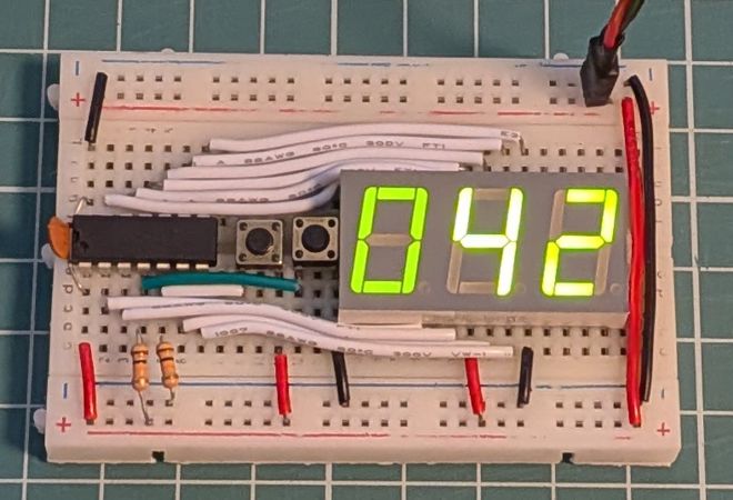
We managed to halve the size of our counter circuit again, and I think this is the smallest size we can achieve on a breadboard.
Although the goal was not a digital handheld counter of usable size, it's still not a bad thing that by the end, we managed to put together something that (with proper packaging) could even be a usable device.
Final settlement
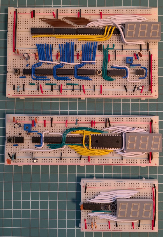
Three and a half breadboards, sixteen ICs, hundreds of wires cut to size, about half a dozen evenings spent tinkering, one burn injury (from overheating caused by a short circuit), and the end result: three digital counters.
- a giant-sized solution using purpose-built chips, where the biggest challenge was all the wires
- a pre-programmed EEPROM version with its own eccentric behavior
- a microcontroller-driven one, where the limited hardware tends to play tricks on careless programmers
Although the solutions decreased in size, the complexity that was present in the first version and plainly visible to the eye did not disappear along the way. It merely migrated into memory and then into the program code.
Recurrence
A press of a button shook Bredbord's delicate balance. The noise born from the bounce reached 555. The energy coursing through the monostable timer opened the path toward charging. Spikes of noise kept biting into him, but 555 held the signal until the rising potential reached such a level that he had no choice but to release it in a discharge. He watched proudly as it departed, merging with the unknown. In spirit, however, he was already preparing for the next assault.
CD4026B awaited the relentless ticking of the approaching clock signal with quiet inevitability. Racing through latches and gates, it changed his inner state. The counter's nine turned over into zero. He returned to where he had begun, to another beginning in the infinite cycle. Although the overflow sent the signal into oblivion, Bredbord had already been tipped out of balance. With that single act, CD4026B had set unstoppable forces into motion. Forces that reached far beyond his own existence.
Split into seven fragments, the change spread onward through the segment pins toward the LEDs of BC56-12. Some fell into the blind void, drifting into a long sleep. Others awakened to a new life, radiant with the excitement of potential. The pattern they formed blazed forth like a divine revelation: once again, balance had been restored. If only for the time being.