Something's in the air
Atomic clocks, radio signals, and time synchronization
The previous clock-building project made me think that there must be a simpler way. So I just bought a desk clock.
Well, that's not exactly how it happened. I just happen to have more than one time-related stuff to do in parallel. This little project, for example, is about how people had access to accurate time before the Internet.
Of course, they looked out of the window and read the time off of the church tower. Thanks to modern technology, we can do this relatively easily. We just point a camera at the church tower and use artificial intelligence to read the time based on the position of the clock hands.

But it's not that simple. Somehow we have to determine whether it is morning or afternoon and it probably wouldn't hurt to know what the date is. Not to mention if there isn't a church tower in sight.
Observant readers may have noticed that I wouldn't need a desk clock for this. Well, yes, that wasn't the direction I was going, I didn't want to go that much back in time. Actually, I wondered how radio-controlled clocks could work.
Radio time synchronization
It all starts with a transmitter tower. From my area, I can pick up the signal sent out by a German tower called DCF77, but there are several other ones covering the whole world.
In the case of the DCF77, the signal is generated from an atomic clock and transmitted in 60 seconds. One bit is received every second. The signal sequence is terminated by an extended pause. However, there is quite a lot of noise, so you may not have enough data when the longer pause arrives, or more likely you may have 59 bits of data before the pause arrives, so depending on reception conditions, it may take quite a while to synchronize.
All we need is a receiver. This is usually done with a ferrite rod antenna and some electronics. It is possible to order a receiver from China, but I didn't want to wait a month and then deal with the local postal service, so the quickest solution seemed to be to order a cheap radio-controlled clock and inspect it.
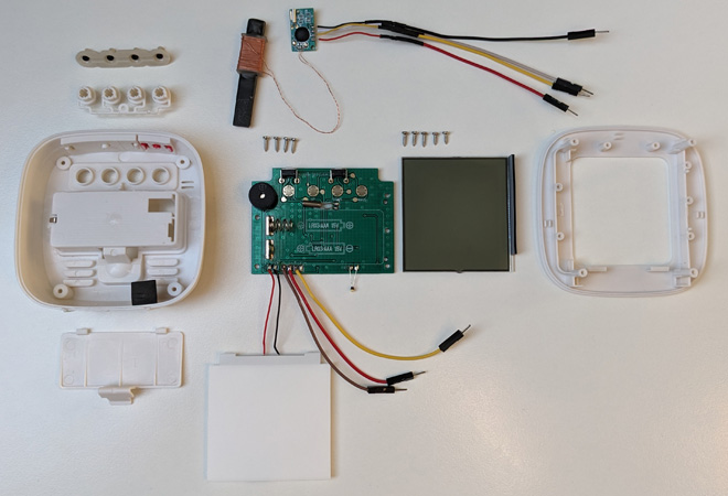
The victim
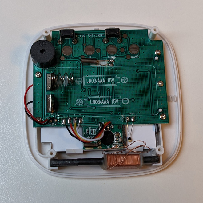
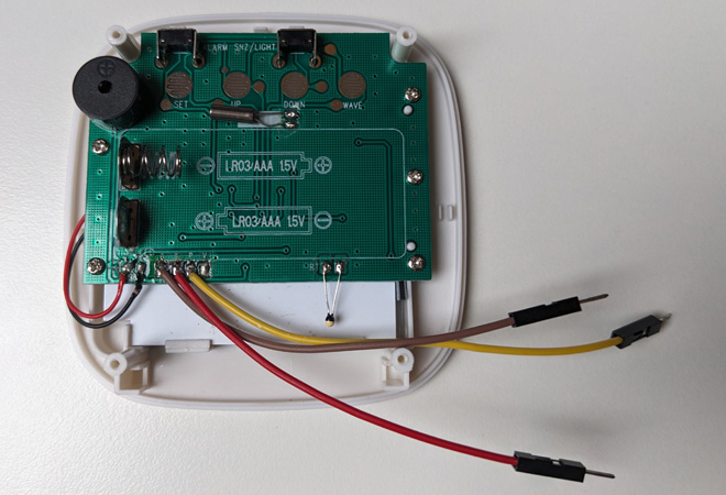
Looking inside the clock mentioned earlier, you can see that there is a separate printed circuit board at the bottom and a ferrite rod antenna underneath it. I soldered them out.
The clock has successfully survived the surgery, everything works the same, except that it has lost its (radio signal) hearing.
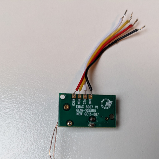
EMAX 6007 V1
GE16-1055R5
NEW GE13-887
The labels on the radio receiver didn't help me to find any description, but based on other similar boards I figured out that the GND goes to ground, you want 3.3 volts on the VCC, the PON can turn the whole module on and off (but doesn't need to be wired anywhere) and we left with the NTCO, so that must be the data.
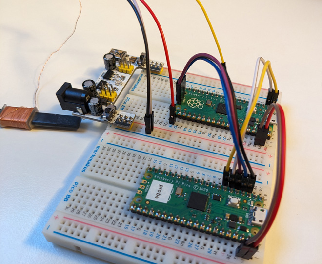
I added some more wires with jumper connectors on the end so I could use it with a breadboard, and then I wired the whole thing to a Pico.
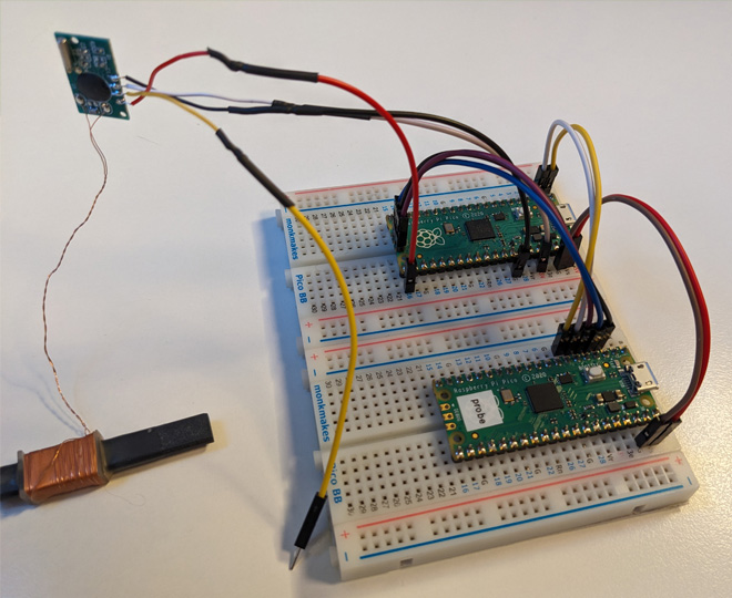
It would have been nice to get it right the first time. I spent a couple of hours here trying to find out why no data was coming from the antenna. I tried searching for any documentation of the module, connected the PON, tried different GPIO pins on the Pico, and even suspected the code, but in the end, I solved it by connecting the module to a dedicated power source and the Pico only received the data signal. Probably the Pico could not supply enough power to the device.
Bits in the noise
We see some kind of data coming in, let's do something with it. At first, I just started flashing the LED on the Pico to get feedback on what was happening.
#include "pico/stdlib.h"

#define DCF_PIN 16
#define LED_PIN 25

void on_change(uint gpio, uint32_t event_mask) {
  gpio_put(LED_PIN, event_mask & GPIO_IRQ_EDGE_RISE);
}

int main() {
  gpio_init(DCF_PIN);
  gpio_init(LED_PIN);

  gpio_set_dir(DCF_PIN, GPIO_IN);
  gpio_set_dir(LED_PIN, GPIO_OUT);

  gpio_set_irq_enabled_with_callback(
    DCF_PIN,
    GPIO_IRQ_EDGE_FALL | GPIO_IRQ_EDGE_RISE,
    true,
    &on_change
  );

  while (true) {
    sleep_ms(1000);
  }
}
The next step is to start measuring how long the signal is high and low. According to the documentation, 0 is received when the signal is high for 100 milliseconds, and 1 is received when the signal is high for 200 milliseconds. Since there is one bit per second, there should be 800-900 milliseconds of low between two high states. In the last second, no data is coming in, so there is a low state for 1800-1900 milliseconds.
First, we define some constant values for noise filtering, to determine whether we got 0 or 1 and to detect the end of the data.
#define MINIMAL_HIGH_PULSE_WIDTH 50
#define MINIMAL_LOW_PULSE_WIDTH 700
#define PULSE_WIDTH_THRESHOLD 150
#define END_OF_DATA_PULSE_WIDTH 1500
Then we will also need some variables to store the time of previous state changes and the data that has arrived so far.
uint32_t rise_time = 0;
uint32_t fall_time = 0;

uint64_t buffer = 0;
uint32_t buffer_position = 0;
After that, we only need to write the inside of on_change. We ask the Pico how many milliseconds have elapsed since it was started.
uint32_t now = to_ms_since_boot(get_absolute_time());
Then we do some noise filtering, otherwise it would be almost impossible to get the time.
if (now - fall_time < MINIMAL_LOW_PULSE_WIDTH) {
  return;
}

if (now - rise_time < MINIMAL_HIGH_PULSE_WIDTH) {
  return;
}
If the signal has gone from low to high, we check to see if the low signal was long enough to indicate the end of the data. If at that point we got 59 bits of data, then all is OK, if not, we start over.
if (event_mask & GPIO_IRQ_EDGE_RISE) {
  rise_time = now;

  if (rise_time - fall_time > END_OF_DATA_PULSE_WIDTH) {
    if (buffer_position == 59) {
      printf(" - data received: %lld\n", buffer);
    }
    else {
      printf(" - reset: not enough data\n");
    }
    buffer = buffer_position = 0;
  }
}
If the signal went from high to low, we decide whether we got a 0 or a 1 based on the length of the signal and store the result in the buffer. Here we may have more data than we need (due to noise), if this is the case we start over.
else if (event_mask & GPIO_IRQ_EDGE_FALL) {
  fall_time = now;

  uint64_t next_bit = fall_time - rise_time > PULSE_WIDTH_THRESHOLD ? 1 : 0;

  printf("%lld", next_bit);

  buffer |= next_bit << buffer_position;
  ++buffer_position;

  if (buffer_position > 59) {
    printf(" - reset: too much data\n");
    buffer = buffer_position = 0;
  }
}
If all goes well, we will have a series of data at the end, hopefully with the current exact time.
The data is flowing in very slowly...
Let's be sure
Noise has been mentioned several times, which can be a big problem. In the room where I have my desktop and servers, I have not even been able to extract any usable data. I had to move to another room with a laptop so I could test the code. During the day there was a lot of noise and it took me half an hour to get the exact time, but in the evening I got the data almost every minute.
So we have a bunch of bits, but we don't know if the fact that we thought we got a 1 actually meant that the other side sent a 1. To check this, there are three parity bits in the data, which are 0 if the data before it has an even number of 1s and 1 if it is odd. First, let's look at how to calculate parity for an arbitrary int:
int parity(int num) {
  num ^= num >> 16;
  num ^= num >> 8;
  num ^= num >> 4;
  num ^= num >> 2;
  num ^= num >> 1;
  return num & 1;
}
I won't go into the details, the Stack Overflow page I stole the code from has a great explanation. Also, we need to know which ones are the parity bits and what data they are calculated on. We can look this up on the related Wikipedia page. For example, for minutes:
int min_data = (int) ((buffer >> 21) & 0b1111111);
int min_parity = (int) ((buffer >> 28) & 1);

if (parity(min_data) != min_parity) {
  printf("invalid parity for minute\n");
}
We shift the buffer to the right by 21 bits (effectively discarding the first 21 bits), because the data for the minute starts at bit 22 and we take the first 7 bits (& 0b1111111) because that's how long the minute data is.
For parity, the first 28 bits are discarded and only 1 bit of the remaining data is retained. The parity we calculate should match the parity we got.
The hour and date are checked similarly, only the number of right shifts and the amount of data retained afterward varies.
int hour_data = (int) ((buffer >> 29) & 0b111111);
int hour_parity = (int) ((buffer >> 35) & 1);

if (parity(hour_data) != hour_parity) {
  printf("invalid parity for hour\n");
}

int date_data = (int) ((buffer >> 36) & 0b1111111111111111111111);
int date_parity = (int) ((buffer >> 58) & 1);

if (parity(date_data) != date_parity) {
  printf("invalid parity for date\n");
}
It's time
Once the buffer has passed the checks, all we need to do is extract the data and set the exact time on the Pico. First, let's look at the minutes here too.
int min = (int) ((buffer >> 21) & 0b1111111);
min = (min >> 4) * 10 + (min & 0b1111);
The extraction of the data is the same as for parity, but since the data is represented as a binary-coded decimal, there is a little extra work to do (the first four bits are the first digit, the second four bits (which are only three in this case) are the second digit).
The rest of the data can be obtained similarly, for the day of the week (dow), Sunday comes as a 7 and Pico wants to get that as a 0. Also, for the year, we have to add 2000 to the value because we only get the last two digits of the year.
int hour = (int) ((buffer >> 29) & 0b111111);
hour = (hour >> 4) * 10 + (hour & 0b1111);

int dom = (int) ((buffer >> 36) & 0b111111);
dom = (dom >> 4) * 10 + (dom & 0b1111);

int dow = (int) ((buffer >> 42) & 0b111);
if (dow == 7) {
  dow = 0;
}

int month = (int) ((buffer >> 45) & 0b11111);
month = (month >> 4) * 10 + (month & 0b1111);

int year = (int) ((buffer >> 50) & 0b11111111);
year = 2000 + (year >> 4) * 10 + (year & 0b1111);
Now we just have to tell the Pico RTC module what the exact time is.
rtc_init();

datetime_t t = {
  .year = (int16_t) year,
  .month = (int8_t) month,
  .day = (int8_t) dom,
  .hour = (int8_t) hour,
  .min = (int8_t) min,
  .sec = 0,
  .dotw = (int8_t) dow,
};

rtc_set_datetime(&t);
And that's it, we've got the exact time without the Internet.
The other direction
We are left with one poor, unfortunate clock that now can't synchronize itself because we've taken the radio module away. Then my dear colleague potato came up with the idea of giving it a fake signal, so I found myself once again unscrewing the clock and soldering some jumper cables in place of the old module. At first just for the GND and NTCO, but later I wired in the PON as well.
I connected it to the Pico and started sending it a signal, but the clock didn't like it so much.
At first, I suspected that it was the lack of the PON connection that was causing the problem, that the clock was getting a signal when it wasn't expecting it, so I plugged that in, but the flashing didn't get any better. Then I suspected the soldering, that I might have accidentally shorted something, but after a few minutes of examining it with a magnifying glass, everything looked fine.
Finally, I became suspicious that the Pico was putting out 3.3 volts and the clock was only running on 3 volts, so maybe 3.3 volts was too much for it. I pulled some resistors from a box, but couldn't find one that solved the problem by itself. After connecting one resistor the situation improved, after two it seemed to be fixed, so I finally connected three just in case.

Now we just need a little bit of code. I tried to replay previously recorded real data, which I repeated every minute, but the clock didn't care. I ran into a few bugs that I sent out the wrong data, but even after correcting these it still didn't work. I tweaked the timing a bit to see if the way I sent it was too accurate or something, but no. In the end, the solution was that the clock wanted to be sure and one data series wasn't enough for it. It needs two successful data series in a row to set the time on itself.
#include <stdio.h>

#include "pico/stdlib.h"

#define DCF_SIGNAL_PIN 12
#define DCF_ENABLED_PIN 13
#define LED_PIN 25

int main() {
  stdio_init_all();

  gpio_init(DCF_SIGNAL_PIN);
  gpio_init(DCF_ENABLED_PIN);
  gpio_init(LED_PIN);

  gpio_set_dir(DCF_SIGNAL_PIN, GPIO_OUT);
  gpio_set_dir(DCF_ENABLED_PIN, GPIO_IN);
  gpio_set_dir(LED_PIN, GPIO_OUT);

  uint64_t buffers[] = {
    //-----PYYYYYYYYMMMMMWWWDDDDDDPHHHHHHPmmmmmmm1AZZARxxxxxxxxxxxxxx0
    0b0000000010010000001111100001001011100000000101000010100001000100,
    0b0000000010010000001111100001001011110000001101000010100001000100,
    0b0000000010010000001111100001001011110000010101000010100001000100,
    0b0000000010010000001111100001001011100000011101000010100001000100,
    0b0000000010010000001111100001001011110000100101000010100001000100,
    0b0000000010010000001111100001001011100000101101000010100001000100,
  };
  int buffer_idx = 0;

  while (true) {
    if (gpio_get(DCF_ENABLED_PIN)) {
      printf("dcf module is not enabled\n");
      sleep_ms(5000);
      continue;
    }

    uint64_t b = buffers[buffer_idx];
    ++buffer_idx;

    int length;
    for (int i = 0; i < 59; ++i) {
      length = b & 1 ? 200: 100;
      printf(b & 1 ? "1" : "0");

      gpio_put(LED_PIN, true);
      gpio_put(DCF_SIGNAL_PIN, true);
      sleep_ms(length);

      gpio_put(LED_PIN, false);
      gpio_put(DCF_SIGNAL_PIN, false);
      sleep_ms(1000 - length);

      b >>= 1;
    }
    printf("\n");

    sleep_ms(1000);
  }
}
I wanted to avoid to implement the data conversion and bit magic so I just used fixed values for the time. Anyway, the clock starts synchronizing after powering on, and after a few minutes, it sets the "accurate" time it got from the "radio signal". The LED on the Pico flashes to the beat of the signal.
I think that's the end of our little journey, we've exhausted almost all the entertainment that a cheap radio-controlled clock can offer. There's also a temperature sensor, a Piezo buzzer, and an LED backlight in it for the ones who need more adventure.