An unexpected recount
ATtiny programming without the Arduino IDE
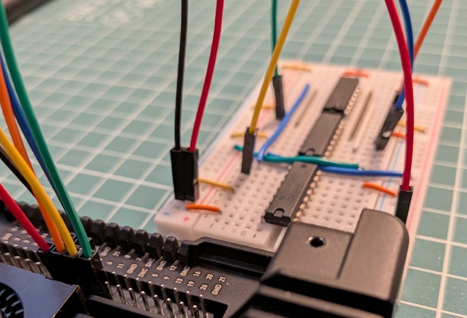
In the previous post, I briefly mentioned that I hadn't managed to upload code to the ATtiny using a Raspberry Pi. At that point, finishing the project was the focus, so I went with the first working solution, but the problem has been bugging me ever since, so here comes act two.
The plan is to get the connection between the Raspberry Pi and the ATtiny working using some new hardware. Then we can get to know the inner workings of the ATtiny a little bit more.
Level shifting
I read somewhere that the Pi's 3.3V GPIO pins might not be enough for the ATtiny, which prefers 5V. To solve this, I ordered a few ICs known as the CD4504:
      ┌───┬──┬───┐
  VCC ┤ • └──┘   ├ VDD
A OUT ┤          ├ F OUT
 A IN ┤          ├ F IN
B OUT ┤          ├ SELECT
 B IN ┤  CD4504  ├ E OUT
C OUT ┤          ├ E IN
 C IN ┤          ├ D OUT
  VSS ┤          ├ D IN
      └──────────┘
It may not be the perfect choice for this purpose, but it might come in handy in other projects later. The point of the chip is that it replaces the voltage received on VCC with the one received on VDD. For example, if 3.3V comes in on VCC and 5V on VDD, then the 3.3V signal arriving at A IN will come out as a 5V signal on A OUT.
With SELECT, we could switch between TTL and CMOS signals, but as far as I understand it, both of our devices are CMOS, so we set SELECT low.
For today's playing around, we'll use an ATtiny84. The ATtiny24 is still embedded in the counter circuit's breadboard. In terms of the pinout, the two are the same. The 84 has a bit more memory.
             ┌───┬──┬───┐
         VDD ┤ • └──┘   ├ VSS
         PB0 ┤          ├ PA0
         PB1 ┤          ├ PA1
PB3 (RESET') ┤ ATtiny84 ├ PA2
         PB2 ┤          ├ PA3
         PA7 ┤          ├ PA4 (SCLK)
  PA6 (MOSI) ┤          ├ PA5 (MISO)
             └──────────┘
Our two-way communication looks like this:
- from the Pi to the ATtiny:
RESET,SCLK,MOSI - from the ATtiny to the Pi:
MISO
Because of this, we use two CD4504s, one converting in the 3.3V->5V direction, the other in the 5V->3.3V direction.
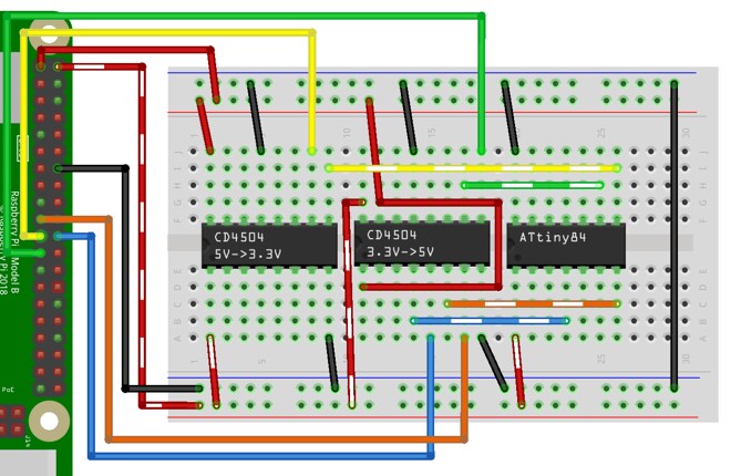
To bring a little clarity to the wiring jungle, the striped wires are 5V, and the solid-coloured ones are 3.3V. The upper part of the breadboard is 3.3V, and the lower part is 5V. The signals coming from the Pi (RESET, SCLK, MOSI) pass through the 3.3V->5V CD4504, and the signal going to the Pi (MISO) passes through the 5V->3.3V CD4504.
Uploading
Let's take a simple program, say the classic blinking LED. We connect the LED to the PA7 pin, turn it on for one second, then off for another one.
blink.c
#define F_CPU 1000000UL

#include <avr/io.h>
#include <util/delay.h>

int main(void) {
  DDRA |= _BV(PA7);

  while (1) {
    PORTA |= _BV(PA7);
    _delay_ms(1000);
    PORTA &= ~_BV(PA7);
    _delay_ms(1000);
  }
  return 0;
}
As you can see, things work a little differently here. The Arduino IDE hides a lot of things from us. We'll return to these in a bit more detail later.
Sending it to the ATtiny won't be just a single button press either. First, we need to install a few packages. For Raspberry Pi OS running on a Pi 5, this was the command I needed:
# apt install avrdude avr-libc gcc binutils
Then we can compile our little program:
$ avr-gcc -mmcu=attiny84 -Wall -Os -o blink.elf blink.c
At this point, we have the option to check whether the program will fit on the ATtiny with the help of the avr-size command:
$ avr-size --format=avr --mcu=attiny84 blink.elf
AVR Memory Usage
----------------
Device: attiny84

Program:     100 bytes (1.2% Full)
(.text + .data + .bootloader)

Data:          0 bytes (0.0% Full)
(.data + .bss + .noinit)
If everything looks good, we can generate the necessary hex file from it:
$ avr-objcopy -j .text -j .data -O ihex blink.elf blink.hex
Which we can finally copy onto the ATtiny:
$ avrdude -p t84 -c linuxspi -P /dev/spidev0.0:/dev/gpiochip0 -x disable_no_cs -B 10kHz -U flash:w:blink.hex
avrdude: AVR device initialized and ready to accept instructions
avrdude: device signature = 0x1e930c (probably t84)
avrdude: Note: flash memory has been specified, an erase cycle will be performed.
         To disable this feature, specify the -D option.
avrdude: erasing chip
avrdude: reading input file blink.hex for flash
         with 100 bytes in 1 section within [0, 0x63]
         using 2 pages and 28 pad bytes
avrdude: writing 100 bytes flash ...

Writing | ################################################## | 100% 0.36 s

avrdude: 100 bytes of flash written
avrdude: verifying flash memory against blink.hex

Reading | ################################################## | 100% 0.34 s

avrdude: 100 bytes of flash verified

avrdude done.  Thank you.
And with that, we'd be done... but since we're already here, let's get to know the ATtiny a bit more closely and rewrite our earlier counter program.
A gentle introduction
I don't plan to go through the chip's complete documentation, which is more than 200 pages long. We'll only look at what is absolutely necessary for our counter. The basis of the whole thing is the registers, through which we can access the various hardware functions. The solution reminded me of the MCP23S17, which we also used in the 286 project. Interestingly, it's even the same manufacturer.
For example, there's the DDRB register, which we can use to set the direction of the pins on port 'B' (PB0-PB3). The indexing corresponds to the place value of the bits, with PB0 being the least significant bit. The PORTB register is used to set the state of the output pins, and we can read the values of the input pins from the PINB register. Similarly, these registers exist for the pins of port 'A', but there are also registers for timers, interrupts, and many others for settings and data.
What's very clear is that we'll be using a lot of bitwise operations. We even get a macro named _BV as a shorthand for bit shifting (it corresponds to the 1 << (bit) operation), which we'll use often in our code.
Recounting
After that much introduction, we can get started on our counter program. The hardware will be the same as before. As a reminder, these are connected to the legs of our microcontroller:
PA0 -> Display pin 12 (Dig1)
PA1 -> Display pin 11 (a)
PA2 -> Display pin 10 (f)
PA3 -> Display pin 9  (Dig2)
PA4 -> Display pin 8  (Dig3)
PA5 -> Display pin 7  (b)
PA6 -> Display pin 5  (g)
PA7 -> Display pin 4  (c)
PB0 -> Display pin 1  (e)
PB1 -> Display pin 2  (d)
PB2 -> Counter button
PB3 -> Reset button
Unfortunately for us, the display pins are all over the ports. I didn't want to rewire the whole project, so we'll have to live with this situation in the code. The ideal setup would probably be for the segment pins and the step button to go on the PA side, and the digit-select pins and the reset button on the PB side.
If we look at the assignment above, the distribution of the segments across the two ports looks like this:
PA | 7 | 6 | 5 | 4 | 3 | 2 | 1 | 0 |
---|---|---|---|---|---|---|---|---|
   | c | g | b | _ | _ | f | a | _ |

PB | 3 | 2 | 1 | 0 |
---|---|---|---|---|
   | _ | _ | d | e |
Our display is common-anode, so we need to send a zero on the segment pin and a one on the digit-select pin for the given segment of the given digit to light up. In the case of the number zero, segments a-f must be zero, and segment g must be one, so we need to write the following values to the two ports:
PA | 7 | 6 | 5 | 4 | 3 | 2 | 1 | 0 |
---|---|---|---|---|---|---|---|---|
   | 0 | 1 | 0 | _ | _ | 0 | 0 | _ |

PB | 3 | 2 | 1 | 0 |
---|---|---|---|---|
   | _ | _ | 0 | 0 |
We won't have to deal with the bits marked by underscores here, so we can write zero in their place.
PA | 7 | 6 | 5 | 4 | 3 | 2 | 1 | 0 |
---|---|---|---|---|---|---|---|---|
   | 0 | 1 | 0 | 0 | 0 | 0 | 0 | 0 |

PB | 3 | 2 | 1 | 0 |
---|---|---|---|---|
   | 0 | 0 | 0 | 0 |
Doing the same for the other digits as well, we'll get the following arrays:
#define F_CPU 1000000UL

#include <avr/interrupt.h>
#include <avr/io.h>

const uint8_t segments_a[16] = {
  0b01000000, 0b01000110, 0b10000100, 0b00000100,
  0b00000010, 0b00100000, 0b00100000, 0b01000100,
  0b00000000, 0b00000000, 0b00000000, 0b00100010,
  0b11100000, 0b00000110, 0b10100000, 0b10100000,
};
const uint8_t segments_b[16] = {
  0b0000, 0b0011, 0b0000, 0b0001,
  0b0011, 0b0001, 0b0000, 0b0011,
  0b0000, 0b0001, 0b0010, 0b0000,
  0b0000, 0b0000, 0b0000, 0b0010,
};
To make things a little more exciting, we'll display a hexadecimal number, so we'll be able to count all the way from 0 to 4095.
const uint8_t pin[3] = { PA0, PA3, PA4 };
uint8_t dig[3] = { 0, 0, 0 };
uint8_t i = 0;

uint8_t stable = 0;
uint8_t samples = 0;
We'll also have a few variables for storing the value, selecting the digit, and filtering out bounce.
And with that, we've arrived at the main function.
int main(void) {
  DDRA = 0b11111111;
  DDRB = 0b0011;

  TCCR1A = 0;
  TCCR1B |= _BV(CS11) | _BV(WGM12);
  OCR1A = 24;
  TIMSK1 |= _BV(OCIE1A);

  sei();

  while (1) {}
  return 0;
}
The function is surprisingly short, but all the more incomprehensible. At least without the nice long documentation.
- With
DDRAandDDRB, we set the direction of ports 'A' and 'B': everything is output, except for the two buttons. - With
TCCR1AandTCCR1B, we start configuring a timer.- With the
CS11andCS12bits (TCCR1B), we can set the timer clock. Since the default value is zero, we only need to set one of them to get 1/8 of the ATtiny's clock. - With the
WGM10,WGM11(TCCR1A),WGM12, andWGM13(TCCR1B) bits, the counter mode can be set. In the mode we set (only theWGM12bit is 1, the others are 0) it will count up to the value found in theOCR1Aregister, then it resets itself to zero.
- With the
- We set the
OCR1Aregister to 25, which causes us to count up from 0 to 24. TIMSK1contains the timer interrupt settings. By setting theOCIE1Abit, we get an interrupt when we reach the value inOCR1A.
Finally, calling the sei() function enables interrupts, and we reach an infinite loop that does nothing.
The ATtiny24 runs at 1MHz[1] and the timer clock will be 1/8 of that, so 125kHz. The counter has to count up 25 steps for one interrupt, so with these settings, we'll get an interrupt every 1/5000 of a second, or every 0.2 milliseconds.
ISR(TIM1_COMPA_vect) {
  PORTA = segments_a[dig[i]];
  PORTB = segments_b[dig[i]];
  PORTA |= _BV(pin[i]);
  if (++i > 2) i = 0;

  uint8_t now = (PINB & _BV(PB2)) ? 1 : 0;
  if (now != stable) {
    if (++samples > 50) {
      stable = now;
      samples = 0;
      if (stable == 1) {
        if (++dig[2] > 0xF) {
          dig[2] = 0;
          if (++dig[1] > 0xF) {
            dig[1] = 0;
            if (++dig[0] > 0xF) {
              dig[0] = 0;
            }
          }
        }
      }
    }
  } else {
    samples = 0;
  }
}
This is our function that gets called by the interrupt, five thousand times per second.[2]
By setting PORTA/PORTB, we display the current digit and advance i to the next digit. We may have a hunch here that the two PORTA modifications could be done in one go, but that can lead to some rather interesting behavior:
PORTA = segments_a[dig[i]] | _BV(pin[i]);
PORTB = segments_b[dig[i]];
In this case, we switch digits before setting the d and e segments on port B to the correct value, so in certain cases, the d and e segments will glow faintly even when they shouldn't.
PORTB = segments_b[dig[i]];
PORTA = segments_a[dig[i]] | _BV(pin[i]);
In this case, the d and e segments on port 'B' get their new value before we switch digits, which leads to a similar problem.
In the original setup, port 'A' gets its value first, but with that, we also turn off all digit selectors. Port 'B' gets its new value, and then we select the new digit. This way, there is no moment in time when a segment would light up in the wrong place.
After refreshing the display, we check the value of the button. If it does not match the current stable value, we increase the number of samples. If we have fifty[3] good samples, then the new value becomes the stable value. If the button was pressed, we increment the value of the digits in the usual way, but now we don't stop at just 9; we go up to 15.
With the stored stable state and the sampling, we ensure that a change in the button's state is only considered valid if the new signal stabilizes for at least 10 milliseconds. So we filter out the bounce that occurs at the moment the button is pressed and released.
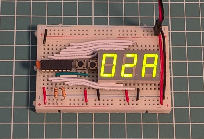
In the way discussed above, we can upload the code to the earlier ATtiny24 used for counting, and become the happy owners of a hexadecimal counter.
Taking stock
We've gotten through this one as well. Yet another counter... who would have thought, after the previous post? With the new code, we managed to make the previous version somewhat better:
- We didn't have to use
PROGMEM. - Instead of 999, we can count up to 4095.
- The debounce protection became more reliable.
- We refresh the digits of the display much faster.
There would still be things to improve if we were bored (for example, not displaying the leading zeros), but my curiosity only drove me this far. Escaping from the Arduino IDE let us get much closer to the hardware. Perhaps closer than we would have liked.
Notes
1. ↑ The default settings, it can be changed with fuses, but that would mess up our calculations.
2. ↑ Writing this down, I started worrying that maybe this function was doing too much, so I did the math, and if everything is true, then even in the worst case, it finishes within 60 clock cycles, and we have 200 clock cycles' worth of time between two interrupts.
3. ↑ You can experiment with the number of samples to find the point where we no longer get false button presses, and the speed of repeated button presses also feels right.