The final countdown
Driving an LCD using an ATtiny microcontroller
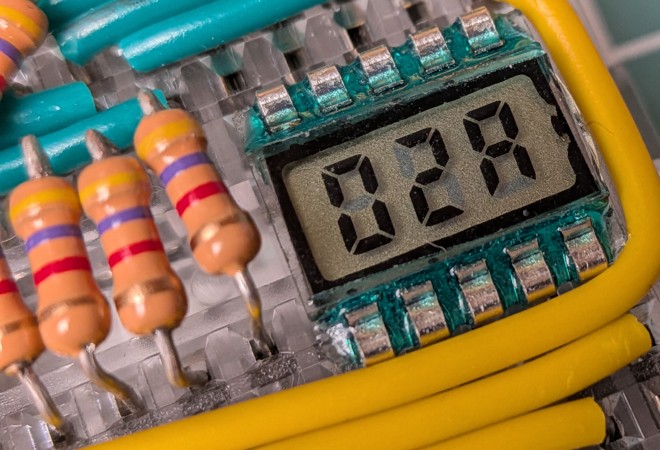
After countless counter content, there's only one loose end left: what happened to those cute little LCD displays?
After about a month and a half of wandering around the world, they finally arrived. I had to straighten each of their pins one by one because the journey had clearly been rough on them, but other than that, they seemed perfectly healthy. Time to finally do something with them.
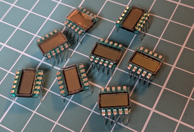
How does an LCD work?
No idea, it must be magic. But after all the adventures, I believe I can at least explain how to make them work. Well, this particular panel, anyway. I have no idea how much of this carries over to other LCDs.
The LED display we used previously had 3 COM pins and 7 segment pins (eight if we count the dot as well, but we ignored that). This LCD has 4 COM pins and 6 segment pins, which already suggests that the COM pins are no longer mapped one-to-one with the digits. Fortunately, there's a table that tells us exactly how the two relate.
| COM / Pin | 1 | 2 | 3 | 4 | 5 | 6 | 7 | 8 | 9 | 10 |
|---|---|---|---|---|---|---|---|---|---|---|
| COM1 | 3D | 2D | 1D | COM1 | ||||||
| COM2 | 3C | 3E | 2C | 2E | 1C | 1E | COM2 | |||
| COM3 | 3B | 3G | 2B | 2G | 1B | 1G | COM3 | |||
| COM4 | 3A | 3F | 2A | 2F | 1A | 1F | COM4 |
There would've even been room for the dot. You can also see that each digit is associated with two pins. The numbering goes from left to right: segment 1D belongs to the leftmost digit, while 3D belongs to the rightmost one. I'm sure coding this will be delightful, but before we get there, this display has a few more quirks.
With LED displays, there are common-anode and common-cathode variants, which determine whether you need to set the segment pin high and the COM pin low, or the other way around. LCDs don't work like that. We have to alternate the polarity every single cycle. And if that weren't enough, the inactive COM pins shouldn't be the opposite polarity of the active one; they need to be held at half the supply voltage.
Let's look at an example. Suppose we want to enable segment 3D, which is at the intersection of COM1 and pin 2. The display requires 3V, so half the supply is 1.5V, and then we have ground at 0V.
- Set the
COM1pin to3V. - Set
COM2-4to1.5V. - Set pin
2to0V. - Set the remaining segment pins (
1,3,4,5,6) to3V. - Wait a little.
- Set the
COM1pin to0V. COM2-4stays at1.5V.- Set pin
2to3V. - Set the remaining segment pins to
0V. - Wait a little, then start the whole thing over again.
To display arbitrary numbers, we simply need to generalize this whole dance:
| Step | COM1 | COM2 | COM3 | COM4 | 1 | 2 | 3 | 4 | 5 | 6 |
|---|---|---|---|---|---|---|---|---|---|---|
| 1. | 3V |
1.5V |
1.5V |
1.5V |
- | 0V |
- | 0V |
- | 3V |
| 2. | 1.5V |
3V |
1.5V |
1.5V |
0V |
3V |
3V |
0V |
0V |
3V |
| 3. | 1.5V |
1.5V |
3V |
1.5V |
0V |
0V |
0V |
0V |
0V |
3V |
| 4. | 1.5V |
1.5V |
1.5V |
3V |
0V |
3V |
0V |
3V |
3V |
3V |
| 5. | 0V |
1.5V |
1.5V |
1.5V |
- | 3V |
- | 3V |
- | 0V |
| 6. | 1.5V |
0V |
1.5V |
1.5V |
3V |
0V |
0V |
3V |
3V |
0V |
| 7. | 1.5V |
1.5V |
0V |
1.5V |
3V |
3V |
3V |
3V |
3V |
0V |
| 8. | 1.5V |
1.5V |
1.5V |
0V |
3V |
0V |
3V |
0V |
0V |
0V |
The COM pins follow a fixed repeating pattern, while the segment pins are determined by the number we're currently displaying. Assuming I haven't messed anything up, repeating these eight steps will display the number 123. You can also see that the first four steps are simply the inverse of the second four.
Now we just have to figure out where we're going to get 1.5V from.
Resistance isn't futile after all
We're going to use two little "tricks". The first is that if we connect two resistors in series between 0V and 3V, we'll get exactly 1.5V between them. What values should the resistors be? I'm sure you could calculate it somehow. I just tried two 47 kΩ resistors, and they worked.
The second "trick" is how we'll switch between the three voltage levels. We're using an ATtiny84 again, whose pins have three possible states: low, high, and high impedance (input mode). If we connect a microcontroller pin to an LCD pin through the two resistors of the voltage divider, then the LCD pin will see 0V when the microcontroller drives it low, 3V when it drives it high, and 1.5V when it's configured as an input.
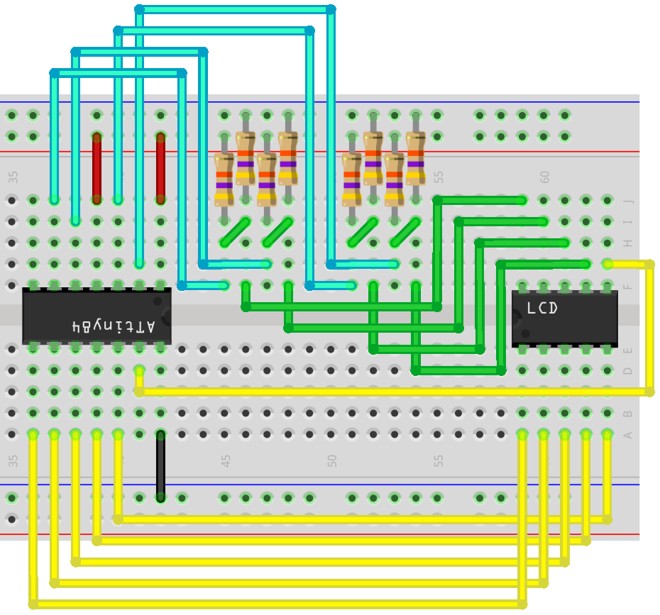
The LCD is substituted with a ten-pin IC
While routing the wires, the main goal was to make the code simpler later on. That's why the poor ATtiny ended up upside down, allowing all the segment pins to land on port A. The COM pins mostly ended up on port B (there isn't enough room there because of the RESET pin), which will also be a little inconvenience during coding. We're not bothering with buttons this time; the program will automatically decrement the counter at regular intervals.
For the physical assembly, I used an even smaller prototyping board, which I regretted multiple times during the wiring. There wasn't much room to work with, but aesthetically, it matches the LCD quite nicely.
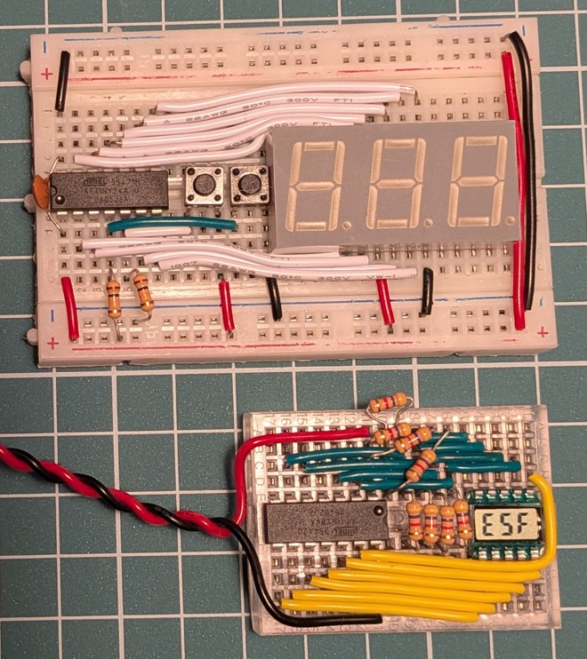
For comparison, you can also see our previous smallest LED version in the photo.
Unfortunately, the pin spacing of the LCD didn't turn out to be completely breadboard-friendly after all, but with a bit of persuasion, I managed to convince it to fit.
Now we can move on to the code. Fair warning: an outrageous amount of bit operations is about to follow. Parental supervision is recommended.
Bit-fiddling
Programming the chip is exactly the same as before. We just have to make the segments work in a completely different way. First, here's a quick summary of how everything is wired together:
| LCD pin | ATtiny pin | Digit | COM1 | COM2 | COM3 | COM4 |
|---|---|---|---|---|---|---|
| 6 | PA0 | 1 | D | E | G | F |
| 5 | PA1 | 1 | - | C | B | A |
| 4 | PA2 | 2 | D | E | G | F |
| 3 | PA3 | 2 | - | C | B | A |
| 2 | PA4 | 3 | D | E | G | F |
| 1 | PA5 | 3 | - | C | B | A |
The digits all follow the same pattern, but the segments of each digit are split across multiple COM lines. Each COM contains two bits of segment data per digit, and with four COM lines, that's exactly eight bits, so we can store the segment data like this:
    | COM4  | COM3  | COM2  | COM1  |
    |-------|-------|-------|-------|
    | F | A | G | B | E | C | D | _ |
|---|---|---|---|---|---|---|---|---|
| 7 | 0 | 1 | 0 | 1 | 0 | 1 | 0 | 0 |
|---|---|---|---|---|---|---|---|---|
| 8 | 1 | 1 | 1 | 1 | 1 | 1 | 1 | 0 |
|---|---|---|---|---|---|---|---|---|
We could put anything in place of the _, I went with zero. That gives us the following values for all the digits:
#define F_CPU 1000000UL

#include <avr/interrupt.h>
#include <avr/io.h>
#include <util/delay.h>

const uint8_t segments[16] = {
    0b11011110,
    0b00010100,
    0b01111010,
    0b01110110,
    0b10110100,
    0b11100110,
    0b11101110,
    0b01010100,
    0b11111110,
    0b11110110,
    0b11111100,
    0b10101110,
    0b11001010,
    0b00111110,
    0b11101010,
    0b11101000,
};
We'll also need a few helper variables:
const uint8_t com_pins[4] = { PA7, PB2, PB1, PB0 };
const uint8_t seg_pins[6] = { PA5, PA4, PA3, PA2, PA1, PA0 };

uint8_t com_idx = 0;
uint8_t direction = 0;

int16_t count = 0xFFF;
The com_idx tells us which COM is currently active, direction decides whether its value is currently zero or one, and count stores the number we're displaying. On to the main function:
int main(void) {
  DDRA = 0b11111111;
  DDRB = 0b0111;

  PORTA = 0;
  PORTB = 0;

  TCCR1A = 0;
  TCCR1B |= _BV(CS12) | _BV(WGM12);
  OCR1A = 15;
  TIMSK1 |= _BV(OCIE1A);

  sei();

  while (1) {
    _delay_ms(1000);
    cli();
    if (--count < 0) {
      count = 0xFFF;
    }
    sei();
  }
  return 0;
}
It's very similar to the previous version. The only real difference is that we've slowed down the timer and decremented the displayed number once every second. With only CS12 enabled, the timer receives the system clock divided by 256 and counts up to 16, so our interrupt function gets called roughly 240 times per second. Because of the four COM lines, that gets divided by four again, giving us a refresh rate of about 60 Hz.
Now let's look at the interrupt function:
ISR(TIM1_COMPA_vect) {
  if (direction) {
    PORTA |= _BV(seg_pins[0]) | _BV(seg_pins[1]) | _BV(seg_pins[2]) | _BV(seg_pins[3]) | _BV(seg_pins[4]) | _BV(seg_pins[5]);
  } else {
    PORTA &= ~(_BV(seg_pins[0]) | _BV(seg_pins[1]) | _BV(seg_pins[2]) | _BV(seg_pins[3]) | _BV(seg_pins[4]) | _BV(seg_pins[5]));
  }

  // ...
}
First, we place all the segment pins into their inactive state according to the current direction.
PORTA &= ~_BV(com_pins[0]);
DDRA &= ~_BV(com_pins[0]);
PORTB &= ~(_BV(com_pins[1]) | _BV(com_pins[2]) | _BV(com_pins[3]));
DDRB &= ~(_BV(com_pins[1]) | _BV(com_pins[2]) | _BV(com_pins[3]));
Then we configure all the COM pins as inputs with no pull-up resistors (high-impedance state).
if (com_idx == 0) {
  DDRA |= _BV(com_pins[com_idx]);
  if (direction) {
    PORTA |= _BV(com_pins[com_idx]);
  } else {
    PORTA &= ~_BV(com_pins[com_idx]);
  }
} else {
  DDRB |= _BV(com_pins[com_idx]);
  if (direction) {
    PORTB |= _BV(com_pins[com_idx]);
  } else {
    PORTB &= ~_BV(com_pins[com_idx]);
  }
}
Next, we switch the COM pin selected by com_idx to output mode and drive it with the appropriate signal for the current direction. Here's the price we have to pay for one of our pins living on port A: it has to be handled separately from the others.
uint8_t seg_value1 = segments[(count >> 8) & 0b1111];
uint8_t seg_value2 = segments[(count >> 4) & 0b1111];
uint8_t seg_value3 = segments[count & 0b1111];

uint8_t dig1 = (seg_value1 >> (com_idx * 2)) & 0b11;
uint8_t dig2 = (seg_value2 >> (com_idx * 2)) & 0b11;
uint8_t dig3 = (seg_value3 >> (com_idx * 2)) & 0b11;

uint8_t data = (dig1 << 4) | (dig2 << 2) | dig3;
Now we calculate the states of the segment pins. At first glance, it looks a little wild, but let's walk through an example to see what it's actually doing. Suppose count is 0x123, which in binary is 0b000100100011.
count >> 8 gives 0b0001, and bitwise ANDing it with 0b1111 still leaves us with 0b0001, which is the digit one.
count >> 4 gives 0b00010010, and bitwise ANDing that with 0b1111 gives 0b0010, which is the digit two.
Finally, count (0b000100100011) bitwise ANDed with 0b1111 becomes 0b0011, which is the digit three.
So we fetch the first, second, and third entries from the segments array:
0b000101000b011110100b01110110
We then shift these values right by 0, 2, 4, or 6 bits, depending on which COM is active, and mask them with 0b11. The result is the green bits for COM1, the blue bits for COM2, the orange bits for COM3, and the purple bits for COM4.
One final left shift and a few bitwise ORs later, we end up with 0b001010 for COM1, 0b011001 for COM2, 0b011111 for COM3, and 0b000101 for COM4. Exactly the bits we need to set for the segments of each respective COM.
for (uint8_t i = 0; i < 6; ++i) {
  if (direction ^ ((data >> i) & 1)) {
    PORTA |= _BV(seg_pins[i]);
  } else {
    PORTA &= ~_BV(seg_pins[i]);
  }
}
By pure coincidence, the pins in the seg_pins array happen to be in exactly the same order as the bits in the data we just assembled, so we simply extract the appropriate bit and set the pin's output according to the current direction.
if (++com_idx > 3) {
  com_idx = 0;
  direction = !direction;
}
Finally, we move on to the next COM, and once we've reached the end of the COM lines, we start all over again with the direction flipped.
0x000
And so we've reached the end. We've run out of numbers.
We've squeezed everything we possibly could out of these counters, and then some. There are no more loose ends left... except for that one particular project whose procrastination started this whole journey in the first place.
Maybe someday we'll finally get to that one, too.